NV type wastewater treatment plants
- Home
- Product
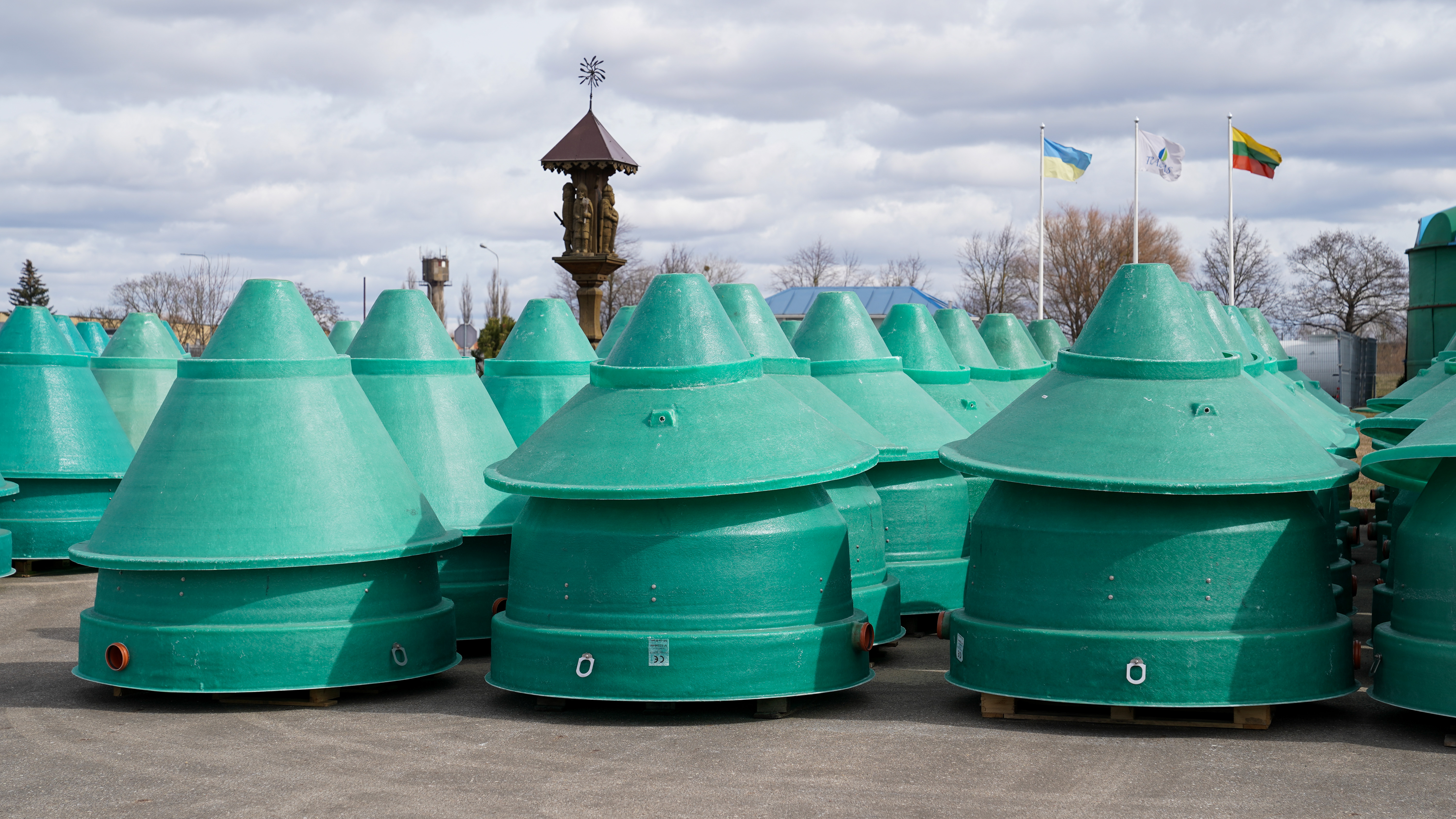
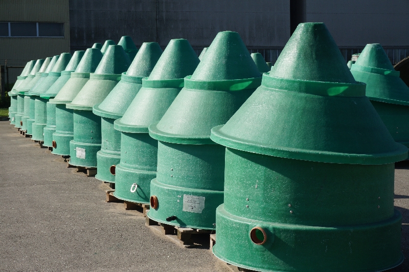
NV type biological treatment facilities of domestic wastewater, sold in Lithuania, Poland, Russia, Macedonia, have been produced since 1996.
NV type aerobic plants are most often used for treatment of domestic wastewater for private houses. Equipment is installed, where there is no possibility of connection to centralised sewage networks.
NV type biological treatment plants of domestic wastewater are intended for treatment of domestic or similar wastewater from the kitchen, bathroom, toilet and other similar-purpose facilities.
Substances that cannot enter the treatment plant are as follows:
- surface wastewater (off the roof, from the yard, etc.);
- wastewater from a garage and other non-domestic – purpose facilities;
- water from a basin or other receptacles that are larger than 1m3;
- chemical substances, entering into sewage system of which is not provided according to their usage (oil products, agrochemical substances, etc.);
- water after regeneration of filters of softening/removal of iron;
- chemicals used at home (washing means, bleaches, softeners, degreasers) shall be use as provided in manufacturer’s recommendations.
Equipment advantages:
- factory enclosed biological treatment unit for domestic waste;
- various capacities;
- high level of treatment, removed 95–98% of pollutants;
- no internal movable parts to be supervised or replaced;
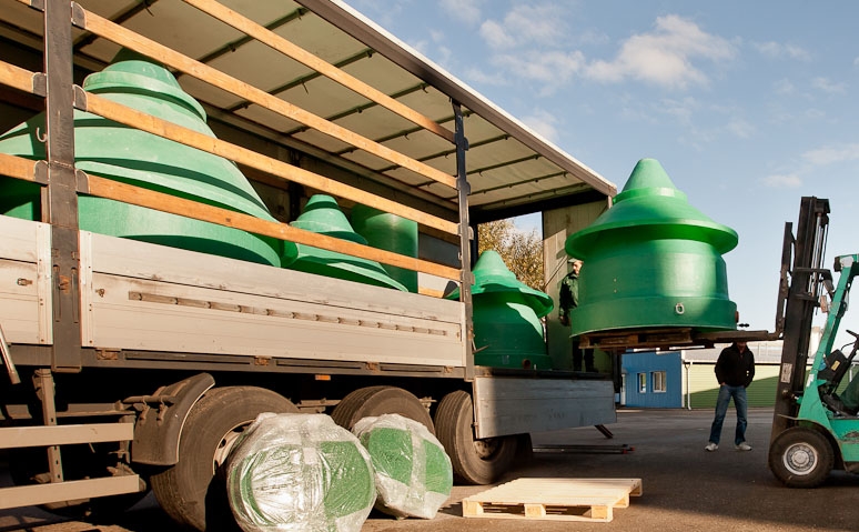
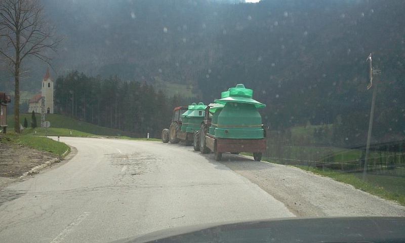
- serviceable, light-weight glass-fibre structure (easy transportation);
- quiet operation and no offensive odour diffusion;
- treated discharged water – transparent and odourless;
- minimum power consumption;
- no need in auxiliary filtering equipment;
- easy maintenance and process automation;
- easy installation.
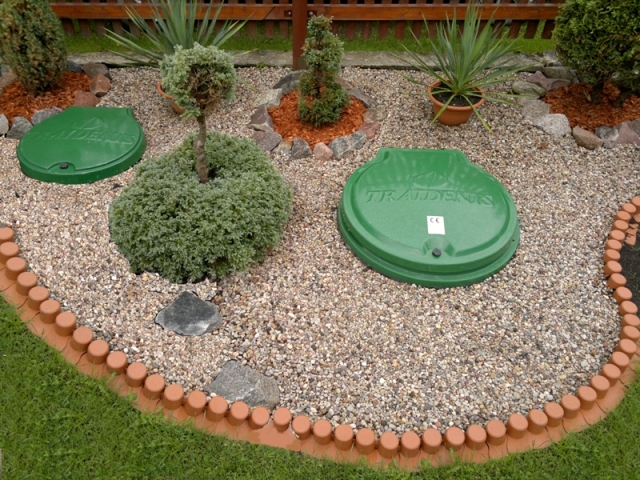
Treatment plant is used as an underground facility. Supplementary collection (riser rings) depends on manifold deepening. Subject to the selected place, treatment plant may be installed in a green lawn or under the roadway (not recommended due to uncomfortable maintenance).
About NV 1÷4a type wastewater treatment plants
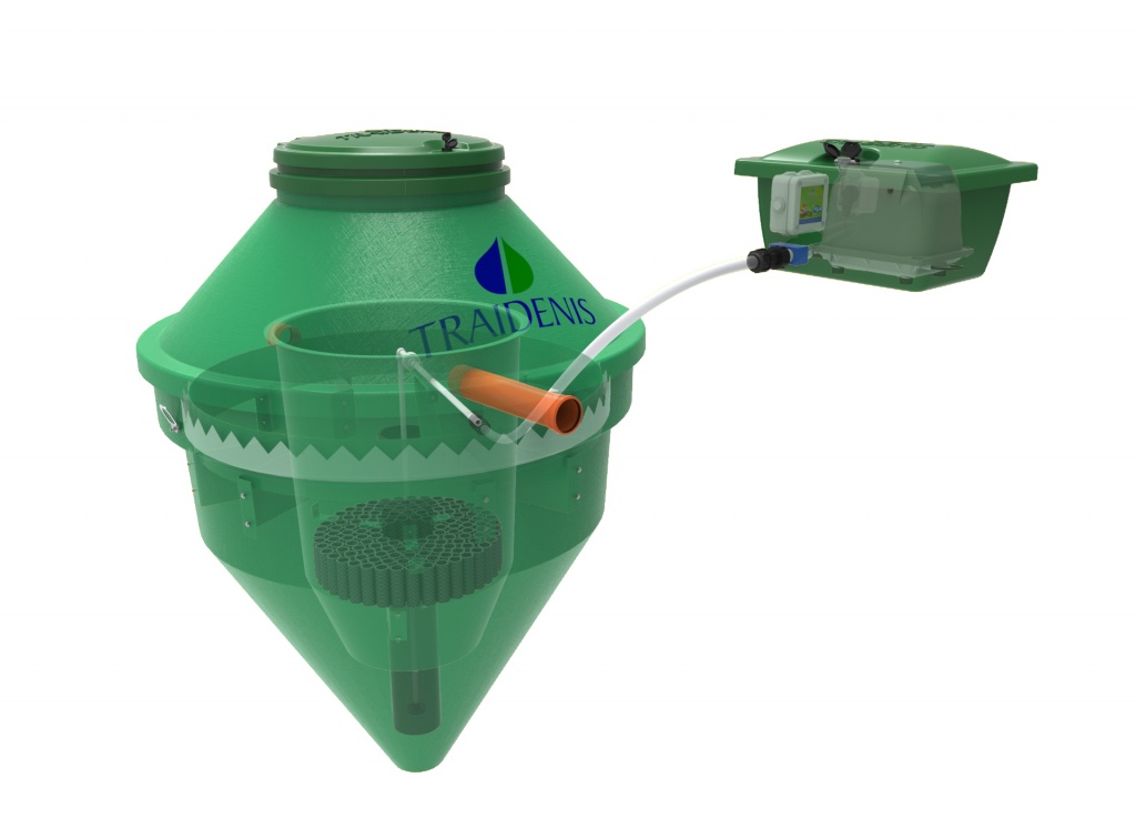
NV 1÷4a type wastewater treatment plant consists of two chambers present in one tank (Figure 1). At first, wastewater, flowing into the plant, enters into the internal chamber, where it is mixed with the activated sludge with the help of air. Compressed air is necessary for supporting life of activated sludge and internal recirculation of treated wastewater. Air is provided with the help of the compressor (airblower). Biological treatment, i.e. treatment with activated sludge, is based on microorganisms’ activities. Purpose of the process is to bind soluble, colloidal and biogenic substances from wastewater into active sludge and separate activated sludge. Flake forming microorganisms multiply and form groups that cause adherence of protozoots and other bacteria. Microorganisms metabolyse (“eat up” and decompose) and destroy organic substances. Decomposition of organic materials and formation of the activated sludge takes place in the aeration section. Mixture of the activated sludge from the aeration chamber enters the external chamber (the secondary settling vessel), where, due to gravity forces, the activated sludge separates and falls down into the bottom part of the plant and the separated treated water lifts up and drains away. If the mass of microorganisms increases, the amount of the activated sludge also increases. Excess sludge is removed by the assenisation machine by pumping-off two-thirds of the plant capacity.
 |
Main structural parts: |
Table of parameters for NV 1÷4a type biological treatment plant of domestic wastewater

 The main dimensions of the treatment plant

The manufacturer reserves the right to change parameters of the product, retaining treatment efficiency.
H* - adjusted according to the required height.
Installation of NV-a type treatment plant of domestic wastewater
Installation site preparation
- Installation of the unit and its performance ensuring systems shall be performed in accordance with technical and/or working project. The designer is responsible for providing calculations, while preparing technical and working projects.
- The lid should be accessible for constant inspection and for proper functioning of the system.
- Check diameter of the sewage pipe. Do maintain a gradient that is required in order to ensure wastewater natural flow to the unit.
- PREPARATION FOR GROUND WORKS: clean a lager site than the treatment plant itself for at least half a metre around it.
- GROUND WORKS: ground works are carried out by strictly following STR 1.07.02:2005 regulation, technical and/or working project and the general construction norms for installation.
In case, when, while ground digging works are performed, units or communications not indicated in the designed drawings are encountered, works shall be immediately stopped and the person performing technical supervision of construction or the authorised person shall be informed. Works in such an area can be continued only after receipt of the permission.
Finishing ground works to the designed altitude, the foundation shall be check for weak or soaked soil, excavations, etc. Such soil shall be removed to the depth indicated by the person performing technical supervision of construction and shall be filled with a proper soil by compaction. The site shall be prepared to the altitude indicated in the project, soil shall compacted (compaction coefficient shall be from 0.95÷0.98, compaction layer shall be 200–300mm).
Installation of NV-a type treatment plant of domestic wastewater
1. Installation of wastewater treatment plant shall be performed following EN 976-2 standard.
2. Treatment plant shall be installed according to the technical and/or working project prepared in advance and harmonized with appropriate institutions.
3. After evaluation of soil properties, an excavation shall follow overhaul dimensions of the plant. Stop digging till 20–30cm to the designed depth of the excavation. Proceed with manual digging that is dig with the spade. This way the unit shall rest on a fixed soil by its bottom.
4. Before lowering the plant to the excavation, IT IS NECESSARY TO CHECK, if the depth of the wastewater feeding pipe and the height of the treatment plant inflow coupling, and angles of the inflow and outflow pipes of the treatment plant do match.
5. The unit shall be lowered to the excavation by using typical lifting mechanisms. After a careful lowering to the excavation, the unit shall be aligned with the help of the lever.

6. For an appropriate performance of the treatment plant it is important for the overflow threshold at the top of it t be horizontal. This is possible by firstly filling the round channel (inner lateral wall is the overflow threshold) at the top with water and by adjusting the position of the whole treatment plant with the help of a level, according to the position of this water surface, in respect of the overflow threshold. Temporary clogging outflow coupling is required for the water not to run-off, when filling the channel.
 |
 |
7. Clearance between edges of the excavation and treatment facility are gradually filled with sand earlier delivered to the installation site that is poured by layers of 20–30cm, by thoroughly compacting with the help of mechanisms. On presence of dry sand, it shall be irrigated during compaction.
8. During installation (or in case of high level of ground water), when pouring sand into the excavation around the unit, the same unit shall be gradually filled with water. This is performed as follows: pour 20–30cm of sand into the excavation around the unit and simultaneously pour 20–30cm of water into the unit. Continue further by pouring 20–30cm of ground into the excavation around the unit and simultaneously pouring 20–30cm of water into the unit.
9. Body of the facility shall be filled with sand to the inflow/outflow branch pipes that are then connected with inflow/outflow pipes.
10. After filling the unit with sand to the upper part of the unit, cap it, in order to prevent the poured sand from entering into the inner part of the treatment plant, when continuing filling works.
11. If unit has been deepened for more than 1.2m, additional rising ring (collected only on necessity) shall be applied. It is pulled without any fastening and sealed by using silicone.
12. Finally, fill all the unit with soil to the designed altitude (recommended: if the unit is installed on the roadway: 50–70mm from the ground surface – if installed on the green lawn in the residential quarter: 200mm – if the unit is installed in an undeveloped territories (STR 2.07.01:2003, Section 450 )).
 |
 |
13. In case of high level of ground water, the unit shall be anchored to the foundation of reinforced concrete. Four anchoring options are available (see Fig. 6: a, b). On lowering the anchoring plate, pour about a layer of sand of 10–20 cm thickness and apply a compaction device. Then mount the unit to the anchoring plate.

Two holes are bored in the ring of reinforce concrete. One end of stainless steel cable is passed through the bored holes, the other one – through holders of wastewater treatment plant. Both ends of the cable are fastened by clamps. Rings of reinforced concrete are laid at a distance from thee unit, in order to form an angle of 20 degrees between the cable and the wastewater plant.

14. When installing the treatment facility under the roadway, a plate of reinforced concrete is fitted (recommended area > 150% of the surface area of the unit), by distributing the transport load off the treatment facilities. While drawing the project, thickness of the plate of the reinforced concrete in every case shall be calculated by evaluating the weight of transport means driving above the facility, transport flow intensity. The designer is responsible for calculations, while preparing technical and working projects.

Installation of the airblower, air inlet pipe and diffusor
- Check, whether there is the necessary airblower model in the set that is described in the description of the treatment plant.
- Airblower can be installed in a utility room (garage, lumber-room, etc.), though no more than at a distance of 15m off the treatment plant, in order to ensure feeding of the required amount of oxygen and to avoid loss of air flow pressure. The room shall be ventilated and installed with electricity. On necessity, compressor may be also mounted outside. Then it is mounted in a special box of glass-fibre, protecting it against rain and dust.
- Mounting the airblower outside, do not place the box in the place, where water is likely to flow in and accumulate.
- Mounting the airblower in a room, place it so that it would not contact wall or any other support.
- Installing air feeding pipe, it is important to prepare of it this much to bypass sharp angles or places, where it would be affected by a too high load with a reserve. It is required to minimize the number of pipe elbows for air to flow with a smooth gradient to the side of the unit, in order to avoid loss of air flow pressure.
Air feeding pipe shall be laid on a harder foundation, for example, on an untouched soil surface in a channel. Fill it with ground carefully, in order to avoid damages.
Your treatment facility requires for constant and scheduled maintenance!
Wastewater treatment facilities produced by Traidenis efficiently cleans wastewater with the help of aerobic microorganisms, decomposing organic pollutants. Proper maintenance results in low frequency of maintenance and low cost price.
Service and maintenance of wastewater treatment facilities shall be performed by qualified personnel. Equipment maintenance (service) personnel shall:
daily check:
- if power is supplied to airblowers; power may be interrupted for up to 10 hours;
- if higher sound or vibration has not occurred;
weekly check:
- if offensive odours have occurred in the unit, check wastewater colour; if a high amount of foam, excess fats or high amounts of biologically undissoluble particles has occurred. If necessary, clean these clusters. It is recommended to check, how the sludge itself and the outflowing water looks like. For this purpose, scoop a little amount of it and monitor sludge: what is its colour, is there offensive odour. Sludge itself in the aeration zone (where intensively mixes wastewater) has to be brown, it should settle well; clear and odourless water should flow out of the unit. If sludge is grey and the particles settle slowly, and water leaving the unit has offensive odour, and is non-transparent – all this shows that sludge is too weak and its performance is unsatisfactory (see Tables of control);
- check sludge concentration in the unit: scoop some water and mixture of sludge in a transparent vessel from the aeration zone and wait for 20–30 minutes, until it shall clear up. Volume of the settle sludge shall be about 30–50% of the common volume of the vessel. On presence of higher volume of the settled sludge, adjust airlift working regime;
- visually check the work of the aeration system (whether intensive mixing of wastewater and the activated sludge takes place);
monthly check:
- check, whether airblower filters are clean, if necessary, clean them or change with new ones (NOTE: a more detail airblower maintenance according to the provided service rules);
- check, whether there is no air leakage in connection places and in the air feeding pipe;
- check the amount of sludge in the thickening unit. When the amount (volume) of sludge is more than 2/3 of the common volume, remove the accumulated excess sludge by pumping off.
quartely check:
- check unit working efficiency: perform control checks for treated and cleaned wastewater;
- monitor amount of excess sludge in the aeration chamber (frequency of pumping off the unit depends on the actual loading with pollutants, but it cannot be less than 1 a year; necessity to pump off is determined in the following way: scoop some water and mixture of sludge in a transparent vessel from the aeration zone and wait for 20–30 minutes, until it shall clear up. Volume of the settle sludge shall be about 30–50% of the common volume of the vessel. When sludge volume exceeds more than 60–70%, remove the excess sludge (it is best to pump off in spring and autumn);
yearly check:
- check, whether air feeding pipes and connections has retained sealed;
- preventive check shall be performed for separate parts of the unit;
Aerator performance shall be checked every 2 years, membrane shall be changed, on necessity; also check the status of bioload, if required, rinse.
Customer or the person providing maintenance services shall fill in service register and register the works in the table of the performed works.
On occurrence of malfunctions or on notice of work disorder of system components, immediately contact representatives of Traidenis UAB. Our specialists shall properly solve the problem, assuring an efficient further operation of the treatment facility.
After maintenance of the unit, ensure that the lid of the treatment plant is closed.
Avoid the following during service of the wastewater treatment unit:
- avoid entering of non-biodegradable particles: paper towels, diapers, handkerchiefs, products from rubber and plastic;
- avoid entering of high amounts of fats;.
- it is forbidden to use domestic chemicals in larger doses than indicated in instructions. Wastewater treatment facility can handle with normal quantities of washing means, whiteners and other domestic chemicals;
- avoid entering of surface and rain water (off the roof, from the yard, etc.) into the unit;
- chemical substances, entering of which is not provided according to their usage (oil products, agrochemical substances, etc.) cannot be discharged into the unit;
- it is crucial to avoid ground water entering the unit. Water should not accumulate around the unit;
- it is recommended not to repair the unit yourself and not to change spare parts upon your discretion.
ATTENTION!
- Do not allow flushing water from filters, intended for softening drinking water and betterment, to enter the unit. Do not allow wastewater after food waste disposer to enter the unit!
- Also do not allow water from basin to enter the unit!
Instruction for removal of excess sludge
When servicing the unit, sludge concentration in the unit (in the aeration zone) should be monthly checked. Scoop some water and mixture of sludge in a transparent vessel from the aeration zone and wait for 20-30 minutes, until it shall clear up. Volume of the settle sludge shall be about 30–50% of the common volume of the vessel. On presence of higher volume of the settled sludge, remove the sludge. Removal of excess sludge depends on modification of the NV type treatment plant of biological wastewater.
NV – A TYPE TREATMENT PLANT OF DOMESTIC WASTEWATER
- Excess sludge may also be removed with the help of assenisation machine directly from the aeration chamber. In this case, firstly, turn off airblower and wait for 30 minutes, until sludge shall settle on the bottom of the unit.
- Disconnect air feeding pipe and turn it off the unit.
- Carefully insert a pull-out hose into the inner part of the unit and pump off everything from the unit. It is not needed to refill the unit with activated sludge after pumping off. Activated sludge attached to the bioload is enough for initial works of the unit after cleaning.
- Reconnect the air feeding pipe and fill the unit with water. IT IS NECESSARY TO DO AT THE SAME DAY. Otherwise, sludge may start fermenting.
- After connecting the air feeding pipe and caping the unit, turn on the airblower.
- Check, whether wastewater mixing in the aeration chamber takes place.
- Other day after cleaning the unit, check, whether there is no offensive odour, foams, how does the sludge looks like.
NV- M TYPE TREATMENT PLANT OF DOMESTIC WASTEWATER WITH BAGS FOR DEWATERED SLUDGE
- Excess sludge is removed from the unit to the bags during the service. Removing is performed in the following manner:
1.1. airblower has to be turned off, air valve feeding air to the aerator has to be screwed-up; wait for 15–20 minutes for sludge to settle at the bottom of the unit; unscrew air valve, with which airblower is connected to the airlift and turn on the airblower.
1.2. preliminary duration of removal of excess sludge is 1–1.5 minutes, until the bag is filled up. After removing the excess sludge, air valve directing air to airlift shall be screwed-up; air valve directing air to the aeration system shall be once again unscrewed. Air once again starts to be delivered to the aerator. The unit shall be returned to the working status.
1.3. When the amount of the thickened excess sludge is about 2/3 of the common volume of the bag, the bag shall be withdrawn and changed with the new one. Sludge accumulated in the bags is treated by unburnt lime (0.5kg of dry unburnt lime into one bag). Then sludge can be disposed as domestic waste. - After removing the sludge, check, whether wastewater mixes in the aeration chamber.
- The other day after cleaning the unit, check, whether there is no offensive odour, foams, how does the sludge looks like.
NV- T TYPE TREATMENT PLANT OF BIOLOGICAL WASTEWATER WITH THE SLUDGE THICKENING DEVICE
- Excess sludge is removed from the unit to the nearby standing sludge thickening device during the operation of airlift by manually switching air flow directing valves. Sludge accumulated in the thickening device is removed with the help of assenisation machine on necessity.
- Airblower has to be turned off, air valve feeding air to the aerator has to be screwed-up; wait for 15–20 minutes for sludge to settle at the bottom of the unit; unscrew air valve, with which the airblower is connected to the airlift and turn on the airblower.
- Preliminary duration of removal of excess sludge is 3 minutes. After removing excess sludge, air valve directing air to airlift shall be screwed-up; air valve directing air to aeration system shall be once again unscrewed. Air once again starts to be delivered to the aerator. The unit shall be returned to the working status. After 10 minutes of unit working, recheck sludge concentration. If concentration is higher than 40%, the process should be repeated.
- Excess sludge thickened in the thickening device shall be removed by the assenisation machine once per three years. Removing the thickened sludge, both sections of the thickening device are pumped off.
- After removing the sludge, check, whether wastewater mixes in the aeration chamber.
- The other day after cleaning the unit, check, whether there is no offensive odour, foams, how does the sludge looks like.
Start-up and adjustment works
- Wastewater treatment plant commissioning works are commenced, when units are recognised as suitable to use and the permission to discharge wastewater into the environment is issued in the valid order (Wastewater treatment regulation No. D1-412 as of 11 September, 2006).
- Duration of commissioning works of units is 3 months from the date of recognizing the unit suitable to use, when air temperature is no less than +10 0C during day-time, and does not fall below 0 0C during night-time.
- Conformity of actual wastewater amounts and contamination to the designed ones shall be checked.
- Aeration system shall be tested in the unit.
- The unit shall be poured with sludge infection by delivering activated sludge or by filling the unit with live (stream, pond) water and growing activated sludge.
- When sludge concentration in the unit reaches ≥ 20%, samples shall be obtained from the outflowing and cleaned water, in order to determine quality.
- Person supervising the units shall be familiarised with the main service rules of the unit.
- Commissioning report shall be drawn.
- During commissioning works the level of up to 50% of treatment of the inflowing primary wastewater contamination according to BDS5 is reached. In this case, during commissioning works, in presence of maximum primary wastewater contamination up to 330 mg/l, contamination of cleaned wastewater according BDS5 may reach up to 165 mg/l.
Service
- Traidenis provides a 20 year warranty for the underground part of the body. Warranty for electrical part is indicated according to the technical passport of the product provided by the manufacturer. The warranty is valid only when servicing and maintaining the unit, by following the unit service and maintenance instruction provided by Traidenis UAB.
- The warranty is provided only for Traidenis production and does not cover expenses, related to failures of house/bureau sewage pipes/collection tanks, distribution system.
- Traidenis shall take no liabilities for failures of the treatment unit, arising due to any reasons of discontinued maintenance of the unit.
- Traidenis offers to sign up the service contract, according to which for a certain service fee our representatives shall regularly (twice a year) come and check the unit and shall eliminate the problems, if any. Regarding the service contract, please contact our representatives.
You will find certificates here.