HNV type biological treatment plants of domestic wastewater for settlements and newly built quarters
- Home
- Product

HNV type domestic wastewater treatment plants for settlements and newly built quarters are intended for treatment of domestic or similar wastewater from the kitchen, bathroom, toilet and other similar-purpose facilities.
Substances that cannot enter the treatment plant are as follows:
- surface wastewater (off the roof, from the yard, etc.);
- wastewater from a garage and other non-domestic–purpose facilities;
- water from a basin or other receptacles that are larger than 1m3;
- chemical substances, entering into sewage system of which is not provided according to their usage (oil products, agrochemical substances, etc.);
- water after regeneration of filters of softening/removal of iron;
- chemicals used at home (washing means, bleaches, softeners, degreasers) shall be use as provided in manufacturer recommendations.
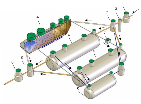
1. Manual grating
2. Sand trap
3. Flow collection/distribution well
4. HNV type wastewater treatment plant
5. Sludge thickener
6. Debit measurement well
7. Airblower
You will find certificates here.
Maintenance
Your treatment facility requires for constant and scheduled maintenance!
Wastewater treatment facilities produced by Traidenis efficiently cleans wastewater with the help of aerobic microorganisms, decomposing organic pollutants. Proper maintenance results in low frequency of maintenance and low cost price.
Service and maintenance of wastewater treatment facilities shall be performed by qualified personnel. Equipment maintenance (service) personnel shall:
daily check:
- control wastewater inlet into treatment plants;
- if power is supplied to airblowers; power may be interrupted for up to 10 hours;
- if the airblower does not overheat;
- if higher sound or vibration has not occurred;
- visually check the work of the aeration system (whether intensive mixing of wastewater and activated sludge takes place);
- check system operation of circulating sludge;
monthly check:
- check, whether airblower filters are clean, if necessary, clean them or change with new ones (NOTE: a more detail maintenance of the airblower is performed according to the provided maintenance rules);
- check, whether there is no air leakage in connection places and in the air inlet pipe;
- concentration of melt oxygen in the unit. On presence of maximum amounts of wastewater, concentration of melt oxygen shall be no less than 1–4mg/l;
yearly check:
- customer or the person providing maintenance services shall fill in maintenance register and shall register the works in the table of the performed works (NOTE: maintenance register is filled-in on daily basis);
Avoid the following during maintenance of the wastewater treatment unit:
- avoid entering of the following non-biodegradable particles into the unit: paper towels, diapers, handkerchiefs, products from rubber and plastic;
- avoid entering of high amounts of grease;
- it is forbidden to use domestic chemicals in larger doses than indicated in instructions; wastewater treatment facility can handle with normal quantities of washing means, whiteners and other domestic chemicals;
- avoid entering of surface and rain water (off the roof, from the yard, etc.) into the unit;
- chemical substances, entering of which is not provided according to their usage (oil products, agrochemical substances, etc.) cannot be discharged into the unit;
- it is crucial to avoid ground water entering the unit; water should not accumulate around the unit;
- it is recommended not to repair the unit yourself and not to change spare parts upon your discretion.
Visual work performance of biological wastewater treatment plant is assessed according to the features of activated sludge and outlet water (see according to the tables of control).
Instruction for removal of excess sludge
Excess sludge is removed from the unit itself, if there is no separate tank for sludge accumulation (sludge thickening device), where sludge is periodically discharged during maintenance.
- Turn-off the airblower from the power network.
- Remove the lid.
- Carefully insert the hose of the assenisation machine in the internal part of the plant and pump-off 50 percent of aeration chamber volume of the mixture of wastewater and sludge from the plant.
- In those plants, where high level of ground water predominates, fill the plant with clean water, by protecting against possible uplift. THIS IS NECESSARY TO BE PERFORMED AT THE SAME DAY.
- Cap the unit and turn on the airblower.
The other day after cleaning the unit, check, whether there is no offensive odour, foams, how does the sludge look like.
Start-up and adjustment works
- Wastewater treatment plant commissioning works are started, when units are recognised as suitable to use and a permission to discharge wastewater into the environment is issued in the valid order (according to the Order No. D1-152 of the Minister of Environment of the Republic of Lithuania dated 26 March, 2008 “On the Amendment of the Order No. D1-412 “On the Approval of the Regulation on the Application of Wastewater Treatment Systems of the Minister of Environment dated 11 September, 2006).
- Duration of commissioning works of units shall be 3 months from the date of recognizing the unit suitable to use, when air temperature is no less than +100C during day-time, and does not fall below 00C during night-time.
- Conformity of actual wastewater amounts and contamination to the designed data shall be checked.
- Aeration system shall be tested in the unit.
- The unit shall be poured with sludge infection by delivering activated sludge or by filling the unit with live (stream, pond) water and growing activated sludge.
- When sludge concentration in the unit reaches ≥ 20%, samples are obtained from the outlet and cleaned water, in order to determine quality.
- Person supervising the units shall be familiarized with the main maintenance rules of the unit.
- Commissioning report shall be drawn.
- During commissioning works the level of up to 50% of treatment of the inlet primary wastewater contamination is reached according to BDS5. In this case, during commissioning works, in presence of maximum primary wastewater contamination up to 400 mg/l, contamination of cleaned wastewater may reach up to 200 mg/l according to BDS5.
Service
- Traidenis provides a 10 year warranty for the underground part of the body. Warranty for electrical part is indicated according to the technical passport of the product provided by the manufacturer. The warranty is valid only when servicing and maintaining the unit, by following the unit service and maintenance instruction provided by Traidenis.
- The warranty is provided only for Traidenis production and does not cover expenses, related to failures of house/bureau sewage pipes/collection tanks, distribution system.
- Traidenis shall take no liabilities for failures of the treatment unit, arising due to any reasons of discontinued maintenance of the unit.
- Traidenis offers to sign up the service contract, according to which for a certain service fee our representatives shall regularly (twice a year) come and check the unit and shall eliminate the problems, if any. Regarding the service contract, please contact our representatives.
- various capacities;
- high level of treatment (removed up to 98% of pollutants);
- no internal movable parts to be supervised or replaced;
- serviceable, light-weight glass-fibre structure (easy transportation);
- small-size enclosed type products;
- quiet operation and no offensive odour diffusion;
- treated discharged water – transparent and odourless;
- minimum power consumption;
- easy maintenance and process automation;
- installation is possible both, under the ground (in case of interference with underground structures) and in a special filling above the ground.
- I modification (HNV-P): primary settling vessel, aerobic reactor, secondary settling vessel;
- II modification (HNV-N): anoxious chamber, aerotank of prolonged aeration, secondary settling vessel.
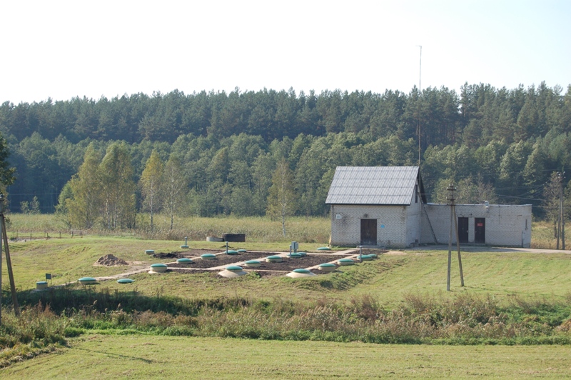
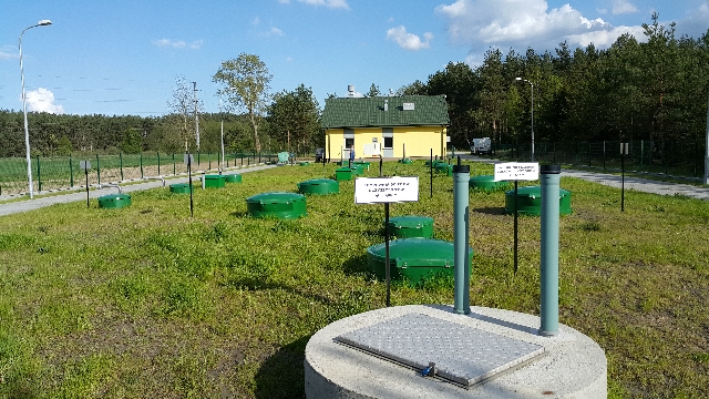
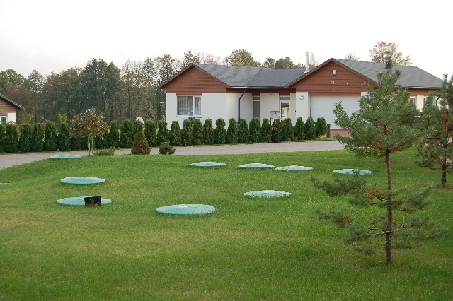
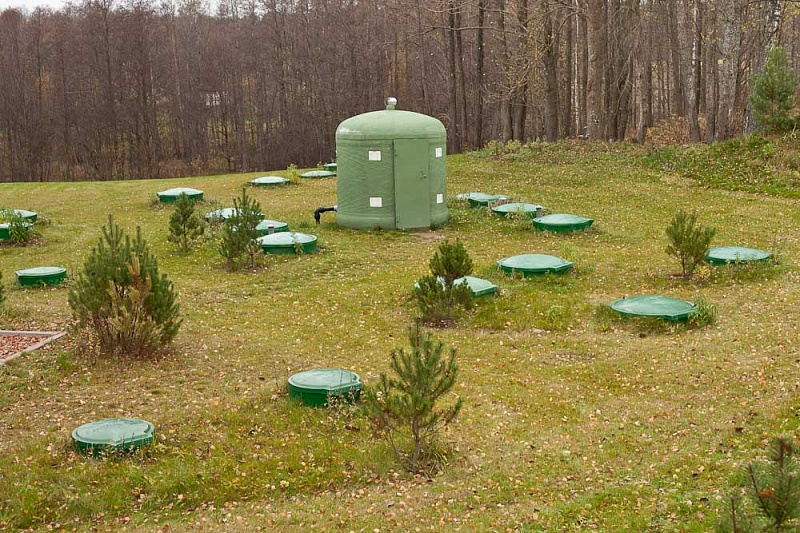
Modular system of HNV type wastewater treatment plant and additional equipment
HNV-P type treatment plants

The plant of HNV-P modification is constructed from a primary settling vessel, an aerobic reactor, a secondary settling vessel (with a module of thin wall) in one tank. Usually, grating (or a pump crusher) and a sand trap are installed before the plant of HNV-P modification.
The fed wastewater enters the primary settling vessel. Wastewater is treated for 2 hours in the primary settling vessel. The sludge settled in the settling vessel with the help of the air pump is constantly removed into a separately fitted sludge stabiliser. After the settling vessel, sludge enters the aerobic reactor with the bioload. Biological treatment, i.e. treatment with activated sludge, is based on microorganisms’ activities. Wastewater, requiring treatment, is aerated. Flake forming bacteria (microorganisms) multiply and form groups that cause adherence of protozoots and other bacteria. Microorganisms metabolyse (“eat up” and decompose) and biologically destroy organic substances. Constant feeding of oxygen is required. Purpose of the process is to bind soluble, colloidal and biogenic substances from wastewater into activated sludge and separate activated sludge. Basically, the process of activated sludge is a live system, thus appropriate actions are required. In order to maintain certain necessary microorganisms, appropriate “feeding, growing, multiplication” is required. Sudden changes in working conditions may result in a shock. Thus, the bioload, to which attach microorganisms that cannot be removed by uneven wastewater flows. Excess sludge from the aerobic reactor is removed into the primary settling vessel with the help of the air pump. After the aerobic reactor, the mixture of wastewater and sludge enters the secondary settling vessel with the thin-walled module, from which the settled sludge is returned into the aerobic reactor with the help of the air pump, and the cleared wastewater drains away from the facility.
Technological schemes of HNV-P type wastewater treatment plants

Technological characteristics

II option. HNV-P type wastewater treatment plants amounts from 25m³/p to 55m³/p (the secondary settling tank in a separate body)

Technological characteristics

HNV - N type treatment plants

The plant of HNV-N modification constructs from an anoxious chamber, an aerotank of prolonged aeration and a secondary settling vessel in one tank. It is necessary to install a grating (a pump crusher), a sand trap, a septic tank and, on necessity, a grease trap against the plant of HNV-N modification.
Anoxious aerobic treatment conditions (oxygen from nitrates is used for biological processes), that is inlet wastewater is mixed with the mixture of nitrified sludge, which is fed from the aeration chamber. Nitrate nitrogen is removed from sludge in the anoxious chamber and settlement of sludge is improved (sludge index and danger of denitrification in the secondary settling vessel decrease). After the anoxious chamber wastewater enters the chamber of prolonged aeration (the aeration reactor), where wastewater is aerated and then aerobic wastewater treatment is performed and excess nitrogen oxidizes into nitrates. The mixture of wastewater and sludge from the aerotank enters the secondary settling vessel, where the separated activated sludge returns to the anoxious section, and cleared wastewater discharges from the facility. Excess activated sludge is periodically removed from the facility, when its concentration reaches the maximum permissible concentration in the aerotank.
The highest wastewater treatment efficiency in achieved in plants of HNV-N modification; they are also easy to service; no green sludge formation, no anaerobic processes take place during wastewater treatment, thus there is no offensive odour diffusion, fully stabilised sludge is removed, due to very low loads of sludge sustained, amounts of excess sludge are lower than of facilities of other modifications.
Technological schemes of HNV-N type wastewater treatment plants
I option. HNV-N type wastewater treatment plants amounts from 5m³/p to 24m³/p (in one body)

Technological characteristics

II option. HNV-N type wastewater treatment plants amounts from 25m³/p to 55m³/p (the secondary settling tank is in a separate body)

Technological characteristics

Treatment efficiency of HNV-N type wastewater treatment plants

Installation of the unit and its performance ensuring systems shall be performed in accordance with the technical and/or working project.
Mounting schemes of HNV type treatment plants
Installation site preparation
We recommend the following:
- installation site for the facility shall be selected so that it would not be flooded by surface waters;
- the lid should be accessible for constant inspection and for proper functioning of the system;
- check diameter of the sewage pipe; do maintain a gradient that is required, in order to ensure wastewater natural flow to the unit;
- PREPARATION FOR GROUND WORKS: clean a larger site than the treatment plant itself at least half a metre around it;
- GROUND WORKS: ground works are carried out by strictly following the STR 1.07.02:2005 regulation, the technical and/or working project and the general construction norms for installation.
In case, when while ground digging works are performed, units or communications not indicated in the designed Schemes are encountered, works shall be immediately stopped. The person performing technical supervision of the construction or the authorised person shall be informed and the works shall be continued only on receipt of the permission.
Finishing ground works to the designed altitude, the foundation shall be checked for weak or soaked soil, excavations, etc. Such soil shall be removed to the depth indicated by the person performing technical supervision of the construction and shall be filled with proper soil by compacting. The site shall be prepared to the altitude indicated in the project, soil shall be compacted (compaction coefficient shall be from 0.95÷0.98, compaction layer shall be 200–300mm).
Installation of the facility
Treatment plant shall be installed according to the project prepared in advance and harmonized with appropriate institutions.
ATTENTION: unit installation requires a special attention, as further performance depends on it.
We recommend the following:
- installation of wastewater treatment plant shall be performed following the EN 976-2 standard;
- stop digging till 20–30cm to the designed depth of the excavation; proceed with manual digging, that is dig with the spade. This way the unit shall rest on fixed soil by its bottom;
- before lowering the plant to the excavation, IT IS NECESSARY TO CHECK, if diameters of couplings match diameters of the wastewater inlet pipe and the treated water outlet pipe; also check, if the depth of wastewater feeding pipe and the height of the treatment plant inlet coupling, and angles of the inlet and outlet pipes of the treatment plant do match;
- the unit shall be lowered to the excavation by using typical lifting mechanisms; after a careful lowering to the excavation, the unit shall be aligned by the help of the lever;
- clearance between edges of the excavation and treatment facility shall be gradually filled with sand earlier delivered to the installation site that is poured by layers of 20–30cm, by thoroughly compacting. On presence of dry sand, it shall be irrigated during compaction;
- during installation (or in case of high level of ground water), when pouring sand into the excavation around the unit, the same unit shall be gradually filled with water; this is performed as follows: pour 20–30cm of sand into the excavation around the unit and simultaneously pour 20–30cm of water into the unit. Continue further by pouring 20–30cm of ground into the excavation around the unit and simultaneously pouring 20–30cm of water into the unit;
- after filling the unit with sand to the upper part of the unit, cap it, in order to prevent the poured sand from entering into the inner part of the treatment plant, when continuing digging works;
- pour sand to the limit for the lid of the treatment plant to be in the same level as street or pavement coating, if the plant is installed on the roadway: 50–70mm from the ground surface – if installed on the green lawn in the residential quarter: 200mm – if the plant is installed in undeveloped territories (STR 2.07.01:2003, Section 450));
- when installing the treatment facility under the roadway, a slab of reinforced concrete of 200mm thickness is fitted, distributing the transport load off the treatment facilities;
- in case of high level of ground water, the unit shall be anchored to the concrete block by a stainless steel belt.
Installation of the airblower, the air inlet pipe and the diffuser
- Airblower can be installed in a utility room, though no more than at a distance of 15m off the treatment plant, in order to ensure feeding of the required amount of oxygen and to avoid loss of air flow pressure. The room shall be ventilated and fitted with electricity. On necessity, the airblower may be also mounted outside. Then it is mounted in a special box of glass-fibre, protecting it against rain and dust.
- Mounting the airblower in a room, place it so that it would not contact wall or any other support.
- Air feeding pipe shall be laid on a harder foundation, for example, on an untouched soil surface in a channel. Fill it with ground carefully, in order to avoid damages.
- Check, if the necessary airblower model, described in the description of the treatment plant, is in the set.
- Mounting the airblower outside, the box cannot be placed in the place, where water is likely to flow-in and accumulate.
- Installing the air feeding pipe, it is important to prepare of it this much to bypass sharp angles or places, where it would be affected by a too high load with a reserve. It is required to minimize the number of pipe elbows that air would flow with a smooth gradient to the side of the unit, in order to avoid loss of air flow pressure.