Scrubbers
- Home
- Wastewater treatment equipment

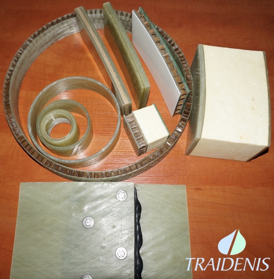
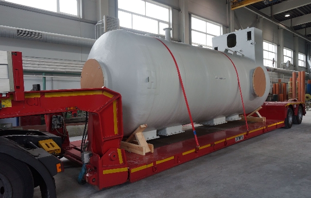
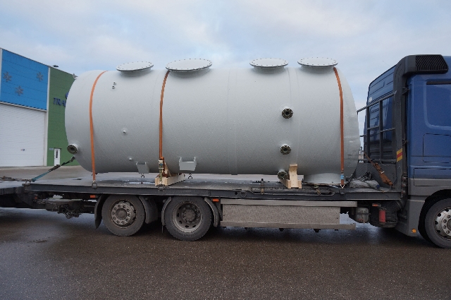
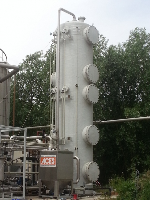
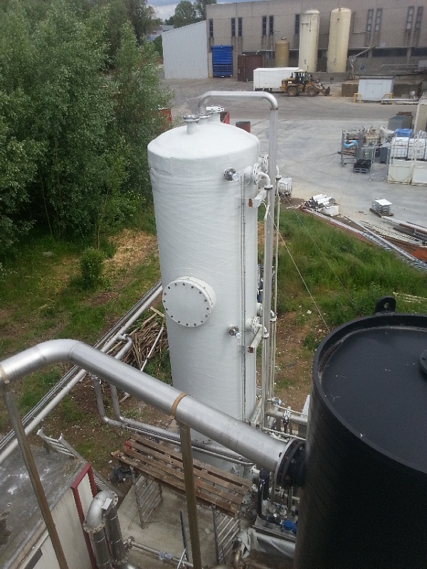
Traidenis produce biogas upgrade tanks to remove undesirable components: carbon dioxide (CO2), hydrogen sulphide (H2S), ammonia (NH3), nitrogen (N2), carbon monoxide (CO). Such a scrubber has two layers of GRP filled with thermal insulation (polyurethane – PU) installed inside the equipment. Such a wall of two-layer GRP construction with 10 cm PU insulation provides 4.8 m²•K/W thermal resistance.
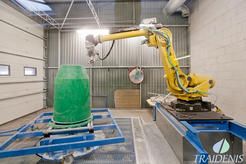
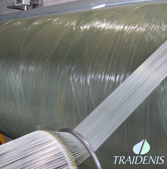
The most important requirement is that scrubber and all it inside parts need to be resistant to aggressive media. Scrubber is produced by using special vinyl ester resin. Biogas plant with biogas flow of 1200 m3/h and capacity 1.6 MW need the scrubber with inside diameter of 4 m, with outside is insulation of 10 cm of polyurethane (PU) coating, which is protected with extra GRP layer to withstand from the natural factors such as rain, snow, wind etc. Bottom of the container above the biogas inlet grille is mounted the fill, which occupies 75 m³ in volume with weight of 26 tons. Biogas goes through the bottom inlet and rising up pass through fill in which the bacteria absorbs the unwanted components of biogas. Container is fitted with flanged connections for the internal equipment installation, inspection and cleaning of ordinary work. The number and size of flanges are produced according to customer requirements or design specifications. Scrubber attached to the foundation, by the anchors at the bottom part. It distributes hydrostatic, wind and snow load, thus reducing their impact on GRP. Calculations of the resistance and the design of each scrubber have been done at Traidenis design - engineer bureau.
Tank installation and its functioning ensuring systems shall be carried out in accordance with construction’s technical and/or working project.
We recommend the following:
- the site for plant installation shall be selected in such a way that it would not be flooded with surface water;
- inspection lid should be available for constant inspection and for proper functioning of the system;
- Do maintain a gradient that is required in order to ensure wastewater natural flow to the unit.
- PREPARATION FOR GROUND WORKS: clean a lager site than the treatment plant itself for at least half a metre around it.
- GROUND WORKS: ground works are carried out by strictly following the STR 1.07.02:2005 regulation, technical and/or working project and the general construction norms for installation.
In case, when, while ground digging works are performed, units or communications not indicated in the designed drawings are encountered, works shall be immediately stopped and the person performing technical supervision of construction or the authorised person shall be informed. Works in such an area can be continued only after receipt of the permission.
Finishing ground works to the designed altitude, the foundation shall be checked for weak or soaked soil, excavations, etc. Such soil shall be removed to the depth, indicated by the person performing technical supervision of construction and shall be filled with a proper soil by compaction. The site shall be prepared to the altitude indicated in the project, soil shall be compacted (compaction coefficient shall be 0.95÷0.98, compaction layer shall be 200–300mm).
Installation of underground tanks
Tanks shall be mounted based on previously prepared project that is already coordinated with respective institutions.
ATTENTION: mounting of tank requires special attention as it conditions the further functioning.
Mounting schemes of horizontal and vertical underground tanks
We recommend the following:
- installation of tank shall be performed following the EN 976-2 standard;
- excavation shall be completed to 20–30cm to the designed depth of the excavation. Proceed with manual digging that is dig with the spade. This way, the unit shall rest on a fixed soil by its bottom;
- before lowering the plant into the excavation, IT IS NECESSARY TO CHECK, if the depth of the wastewater feeding pipe and the height of the treatment plant inflow coupling, and angles of the inflow and outflow pipes of the treatment plant do match;
- the unit shall be lowered to the excavation by using typical lifting mechanisms. After a careful lowering to the excavation, the unit shall be aligned with the help of the lever;
- The gap between the edges of the excavation and the tank shall be gradually filled with sand, transported the installation site in advance, which is filled up by layers of thickness of 20–30cm and carefully compacted. Dry sand shall be compacted by watering it.
- during the mounting stage (or in case of high level of ground water), when filling sand into the excavation around the tank, water shall also be filled gradually into the tank at the same time. It shall be performed in the following way: 20–30cm of sand shall be filled into the excavation around the tank and at the same time 20–30cm of water shall be filled into the tank. The procedure shall be repeated further by filling 20–30cm of ground around the tank and 20–30cm of water to the same tank.
- When the tank is covered with sand until the upper part, place the lid, so that the sand would not access the inside of the tank, when performing back-filling works.
- Fill such amount of sand that inspection lid of the tank would be in one level with the cover of the street or the pavement, if the unit is installed on the roadway: 50–70mm from the ground surface – if installed on the green lawn in the residential quarter: 200mm – if the unit is installed in an undeveloped territories (STR 2.07.01:2003, Section 450 ).
- When mounting the tank under the roadway, armoured reinforced concrete slab of the thickness of 200mm that distributes the load of transport means from the tank is placed above it.
- In case of high ground water level, the tank shall be anchored to the reinforced concrete slab with stainless steel belt.
Instruction for lowering and installation of tanks
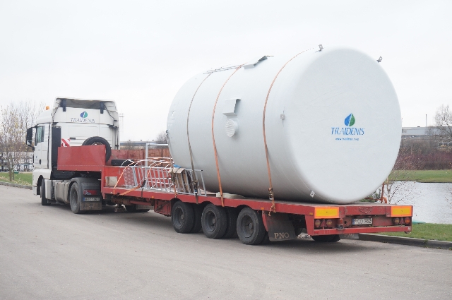
All works of transportation, lifting and placement of vertical tanks shall be carried out in accordance with the Lithuanian standard LST EN 13121-4:2005/AC:2008.
Necessary facilities and equipment:
- two automobile cranes. One of cranes shall be with the lifting height higher than 15m;
- crossarm (lifting the weight of tank, t) and of Dm length;
- strops, 2 units (in addition to crossarm) and 1 unit of “back” strop corresponding to the lifted weight (the lengths of strops are indicated in the technical project and are individual for each tank);
- “back” strop shall be of belt or textile type in order to avoid damage to tanks;
- turret for attaching and detaching strops.
Lowering and installation of the tank:
- belt and textile type “back” strop shall be winded around the tank between brackets and attached to the crane hook;
- crossarm with strops shall be attached to loops behind the two opposite suspension brackets;
- tank is taken down and further taken as it is shown in the lifting scheme (Fig. Scheme for lowering and installation of the tanks) without placing it on the ground;
- when placing into vertical position, the scaffolding crane is unhooked and the unit is placed into necessary area, by using the other crane.
 Scheme for lowering and installation of the tanks
Selection of fitting elements and anchoring bolts
Anchoring bolts are necessary for tank for the wind not to roll it over. The highest likelihood for the tank to be rolled over is when strong wind is blowing, it is empty and no snow is present on the top.
Reactions occur in the fitting element due to wind pressure. Vertical reaction is namely the force of pulling out the anchorage bolt. Based on this force, dimensions of anchorage bolt shall be selected. The CUSTOMER presents the construction of fitting elements.
 |
 |
Example of the fitting element
Note: dimensions of anchorage elements and bolts, their location and quantity are selected individually in each particular case or in accordance to the technical project.
You will find certificates here.